To control the power outlets there is a library for Arduino. It's called rc-switch. With these library you can control 433MHz receivers as well as transmitters. There are some examples included to show how the library works.
Transmission protocol
At first I want to explain the basics of the used transmission protocol. The transmitter sends a sequence of bits as HIGH or LOW level. This sequence isn't seen as a binary sequence (only 0 and 1) but as a so called tri-state-sequence. As you can guess by the name, it has THREE STATES. Besides 0 and 1 there is a state called F (F for "floating"). A tri-state-bit is represented by a sequence of HIGH-LOW-HIGH-LOW levels. The order of HIGH and LOW is always the same, the bits are differed by the length of HIGH and LOW level. Either the HIGH phase is longer than the LOW phase or vice versa:
_ _ _ _
| | _ or | | _ _ _
The three states:
_ _
| | _ _ _ | | _ _ _ means 0
_ _ _ _ _ _
| | _ | | _ means 1
_ _ _ _
| | _ _ _ | | _ means F
When the user pishes a button on the remote control, it sends the adress of the desired power outlet and the command ("on" or "off"). The transmission is ended with a sync bit.
rc-switch and the power outlets
Actually we don't have to deal with this stuff because rc-switch (our library) supports all kinds of power outlets out of the box.
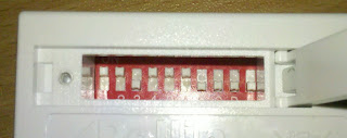
You can set the adress of the power outlet using DIP switches:
If you would use the included remote contol, you would have to set the "system code" using the first 5 switches. With the other 5 switches you can decide wheter the outlet is outlet A, B, C, D or E.
Since we don't use the included remote controle, we don't have to care about this. You can just enter any desired code (in my case it's 11011'10000).
Now you can connect the transmitter module to VCC, GND and a pin of your Arduino and load the following code to the Arduino:
#include <RCSwitch.h>

RCSwitch mySwitch = RCSwitch();

void setup() {

  //transmitter is connected to pin 10
  mySwitch.enableTransmit(10);

}

void loop() {

  //switch power outlet on
  //first parameter is the position of the first 5 DIP switches
  //second parameter is the position of the last 5 switches
  mySwitch.switchOn("11011", "10000");

  //Wait...
  delay(1000);

  //switch power outlet off
  mySwitch.switchOff("11011", "10000");

  //Wait...
  delay(1000);

}
In the setup() function we tell the programm to which pin we connected the transmitter. In loop() we switch on the power outlet, wait for a second, switch it off, wait again and so on.
The commands switchOn and switchOff convert its parameters to a sequence of tri-state-bits, containing the adress and the command: a 1 in the parameter is converted to a 0 in the tri-state-sequence, a 0 will be a F. If we would convert the adress of the used power outlet, it would be: 00F00'0FFFF. The command for switching on the outlet is 0F, the one for switching it off is F0.
So you could replate the switchOn- and switchOff-commands with the sendTriState()-command also included in the library:
void loop() {

  //switch on
  mySwitch.sendTriState("00F000FFFF0F");

  //wait...
  delay(1000);

  //switch off
  mySwitch.sendTriState("00F000FFFFF0");

  //wait...
  delay(1000);

}
If you don't like tri-state-bits and prefer "real" binary bits, you could convert the tri-state-forman to binary format:
00F00'0FFFF'0F would be 0000010000'0001010101'0001 and 00F00'0FFFF'0F would be 0000010000'0001010101'0100. These sequences could be sent using the command
mySwitch.send("000001000000010101010001");

No comments:
Post a Comment