AdSense

Showing posts with label Home Automation. Show all posts

Sunday, 30 August 2020

Home Automation with a Raspberry PI and ESP8266, part 2: A simple sensor (ESP8266)

(Deutsche Version) As the first project, I want to show my temperature and humidity sensors. I use an ESP8266 who reads a Si7021 sensor. The Si7021 is connected with a 4 pin cable to the ESP on pins D1-D4, as you can see in the image:

Additionally, you have to connect the pin D0 to RST, so deep sleep works, which we will use later. Using quite cheap phone chargers, I used a capacitor parallel to G and 3V.

This is placed in a 3d printed housing that you can find on thingiverse: https://www.thingiverse.com/thing:4583759. The sensor is fixed with the small hook in the housing. afterwards the ESP is placed on top and the lid fixes everything. The open side is suited to connect a phone charger.


The code is comparable to the one on my last post about this topic, https://physudo-e.blogspot.com/2019/07/wifi-thermometer-with-dht22-and-eps8266.html. In the setup part, the wifi is connected. If this does not work, the ESP is resetted after 100 seconds. Additionally, the Si7021 sensor is initialized.

In loop, if the WiFI is connected (otherwise the ESP is resetted), the temperature and humidity is measured. If anything goes wrong here, the ESP is resetted, too. Afterwards, everythin is sent via http request to the Raspberry PI as described in the previous post (https://physudo-e.blogspot.com/2020/08/home-automation-with-raspberry-pi-and.html).

#include <ESP8266WiFi.h>
#include <ESP8266HTTPClient.h>
const char* ssid     = "WIFI SSID";
const char* password = "WIFI PASSWORD";

#include "Adafruit_Si7021.h"

Adafruit_Si7021 sensor = Adafruit_Si7021();

void setup()
{
  Serial.begin(9600);

  Serial.print("Your are connecting to;");
  Serial.println(ssid);

  WiFi.begin(ssid, password);

  int resetCtr = 0;
  while (WiFi.status() != WL_CONNECTED)
  {
    delay(500);
    resetCtr ++;
    Serial.print(".");
    if (resetCtr > 200)
    {
      ESP.restart();
    }
  }

  pinMode(D0, WAKEUP_PULLUP);
  pinMode(D3, OUTPUT);
  pinMode(D4, OUTPUT);
  digitalWrite(D3, HIGH);
  digitalWrite(D4, LOW);
  delay(500);

  while (!sensor.begin())
  {
    Serial.println("Did not find Si7021 sensor!");
  }

  digitalWrite(D3, LOW);
}


void loop() {
  if (WiFi.status() != WL_CONNECTED)
  {
    ESP.restart();
  }

  if (WiFi.status() == WL_CONNECTED)
  {
    Serial.println("");
    Serial.println("Your ESP is connected!");
    Serial.println("Your IP address is: ");
    Serial.println(WiFi.localIP());

    digitalWrite(D3, HIGH);
    delay(500);
    float t = sensor.readTemperature();
    Serial.print("Temperature: ");
    Serial.println(t);
    float h = sensor.readHumidity();
    Serial.print("Humidity: ");
    Serial.println(h);
    if (isnan(t))
    {
      t = sensor.readTemperature();
    }
    if (isnan(h))
    {
      h = sensor.readHumidity();
    }
    digitalWrite(D3, LOW);

    if (isnan(t))
    {
      ESP.restart();
    }
    if (isnan(h))
    {
      ESP.restart();
    }


    HTTPClient http;
    char requestString[255] = "";
    sprintf(requestString, "http://raspberrypi/SendValues.php?name=Temperatursensor_1&split=1&data=%f,%f", t, h);    
    http.begin(requestString);
    int httpCode = http.GET();
    Serial.println(httpCode);

    if (httpCode > 0)
    {
      String payload = http.getString();
      Serial.println(payload);
    }

    http.end();

    ESP.deepSleep(300e6); 
    delay(300000);
    ESP.reset();
  }
  else
  {
    Serial.println("");
    Serial.println("WiFi not connected");
    delay(1000);
  }
}

Home Automation with a Raspberry PI and ESP8266, part 1: Basics (Raspberry PI)

(Deutsche Version) Today, I want to start presenting my smart home system. I started half a year ago and by now, the system has grown quite big. The current system consists of:

  • 6 temperature- and humidity sensors inside
  • 3 temperature- and humidity sensors outside
  • 2 temperature- and humidity sensors in our terrarium
  • 1 CO2 sensor
  • 5 switchable plug sockets
  • 3 switchable lamps
  • 1 switch for the input of the sound system
  • Sensors at the washing mashine and tumble dryer
  • Microphone and two cameras at the 3d printer
  • Dashboard as website on an old tablet resp. on the smartphone
  • Telegram bot with automatic alerts and commandos

The basic for everything is a Raspberry PI 4, who acts as a server in the WiFi. All data is stored here, the website is placed here and all sensors communicate with the Raspberry. You don't have to setup much on the raspberry, I installed the apache2 webserver, you can find a lot of tutorials on this topic on the internet. Basically it can be condensed to this one command:

sudo apt install apache2

Additionally, I installed apache2 for php with this command:

sudo apt-get install php libapache2-mod-php

These are all the requirements on the Raspberry. I recommend to setup the folder /var/www/html/ as a network share, then you can access all files and scripts from other computers. Additionally, you should create the folder /var/www/html/data/, all data files are located here.

Now we can start with the scripts. I will only describe the basic script to send data, all other modifications and scripts will be presented with the relevant posts. To send data, I use the file "SendValues.php", which requests the following GET parameters from the sensor:

  • "name", the name of the sensor, e.g. "TemperatureSensor_1"
  • "split", how the data should be split. The problem would be files accumulating the data over years, making them very big and hard to handle. Therefore, the data is split by year, month or day. Split 0 means no splitting, 1 equals one file per year, 2 one file per month and 3 one file per day
  • "data", the relevant data, separated by comma, e.g. for a temperature and humidity sensor: 24.1,54.6

The script consists of the following parts. At first the header:

<html>
 <head>
  <title>Send Sensor Values</title>
 </head>
 <body>
  <?php 

Afterwards the relevant code. Here the data is read and the current date is determined:

$name = htmlspecialchars($_GET["name"]);
$split = htmlspecialchars($_GET["split"]);
$data = htmlspecialchars($_GET["data"]);

$date = gmdate("Y-m-d") . "T" . gmdate("H:i:s.u") . "Z";

Now, a [name]_last.csv file is created, which holds the newest value:

$file = "data/".$name."_last.csv";
$Saved_File = fopen($file, 'w');
fwrite($Saved_File, $date . "," . $data . "\r\n");
fclose($Saved_File);

Next, the splitting is performed. Therefore the filename is created, [name]_[year]-[month]-[day].csv. To have an overlap between two files, the next file is also created, for the next year, next month, next day and already holds the values. If e.g. the last year is requested this guarantees that every file contains at least one year of data, not only the values starting from January 1st. $file1 is the current file, $file2 the one for the next time period.

$file = "data/".$name.".csv";

if ($split == "1")
{
  $file = "data/".$name."_" . gmdate("Y") . ".csv";
  $file2 = "data/".$name."_" . gmdate("Y", strtotime("+1 year")) . ".csv";
}
if ($split == "2")
{
  $file = "data/".$name."_" . gmdate("Y-m") . ".csv";
  $file2 = "data/".$name."_" . gmdate("Y-m", strtotime("+1 month")) . ".csv";
}
if ($split == "3")
{
  $file = "data/".$name."_" . gmdate("Y-m-d") . ".csv";
  $file2 = "data/".$name."_" . gmdate("Y-m-d", strtotime("+1 day")) . ".csv";
}

Now the data is saved. If "split" is 0, the saving into the second file is skipped as there only exists one single file for the whole time.

$Saved_File = fopen($file, 'a');
fwrite($Saved_File, $date . "," . $data . "\r\n");
fclose($Saved_File);
if ($split == "0")
{
}
else
{
  $Saved_File = fopen($file2, 'a');
  fwrite($Saved_File, $date . "," . $data . "\r\n");
  fclose($Saved_File);
}

This already was the whole code, we now have to close all the tags and then SendValues.php is completed:

  ?>
 </body>
</html>

This is all you need on the server site, now the sensors can send their data. To test this, you can put the following text into your browser within your WiFI, this should create the files TemperatureSensor_1_last.csv, and two additional files with the current and the next year at the end:

http://raspberrypi/SendValues.php?name=TemperatureSensor_1&split=1&data=25.3,64.59

For everyone not wanting to copy the code parts, here is the complete code:

<html>
 <head>
  <title>Send Sensor Values</title>
 </head>
 <body>
  <?php
 
$name = htmlspecialchars($_GET["name"]);
$split = htmlspecialchars($_GET["split"]);
$data = htmlspecialchars($_GET["data"]);

$date = gmdate("Y-m-d") . "T" . gmdate("H:i:s.u") . "Z";

$file = "data/".$name."_last.csv";
$Saved_File = fopen($file, 'w');
fwrite($Saved_File, $date . "," . $data . "\r\n");
fclose($Saved_File);

$file = "data/".$name.".csv";

if ($split == "1")
{
  $file = "data/".$name."_" . gmdate("Y") . ".csv";
  $file2 = "data/".$name."_" . gmdate("Y", strtotime("+1 year")) . ".csv";
}
if ($split == "2")
{
  $file = "data/".$name."_" . gmdate("Y-m") . ".csv";
  $file2 = "data/".$name."_" . gmdate("Y-m", strtotime("+1 month")) . ".csv";
}
if ($split == "3")
{
  $file = "data/".$name."_" . gmdate("Y-m-d") . ".csv";
  $file2 = "data/".$name."_" . gmdate("Y-m-d", strtotime("+1 day")) . ".csv";
}
$Saved_File = fopen($file, 'a');
fwrite($Saved_File, $date . "," . $data . "\r\n");
fclose($Saved_File);
if ($split == "0")
{
}
else
{
  $Saved_File = fopen($file2, 'a');
  fwrite($Saved_File, $date . "," . $data . "\r\n");
  fclose($Saved_File);
}

  ?>
 </body>
</html>

Tuesday, 11 August 2020

Machine Learning for a camera surveilled 3d printer

(Deutsche Version) It's been now over a year since the last post and I did lots of projects, especially with the multi-colour upgrade for my Ultimaker 2+. Today, I want to share a project that is part of this, but also part of my IoT Home Automation system: A (two) camera based surveillance for my 3d printer with automated recognition of states.

First of all: the cameras. I have two ESP32-Cam modules where you can find endless tutorials on the internet on how to program these. I then added them to my 3d printer. The first camera is on top, with a 3D-printed fixture you can find here: https://www.thingiverse.com/thing:3899159

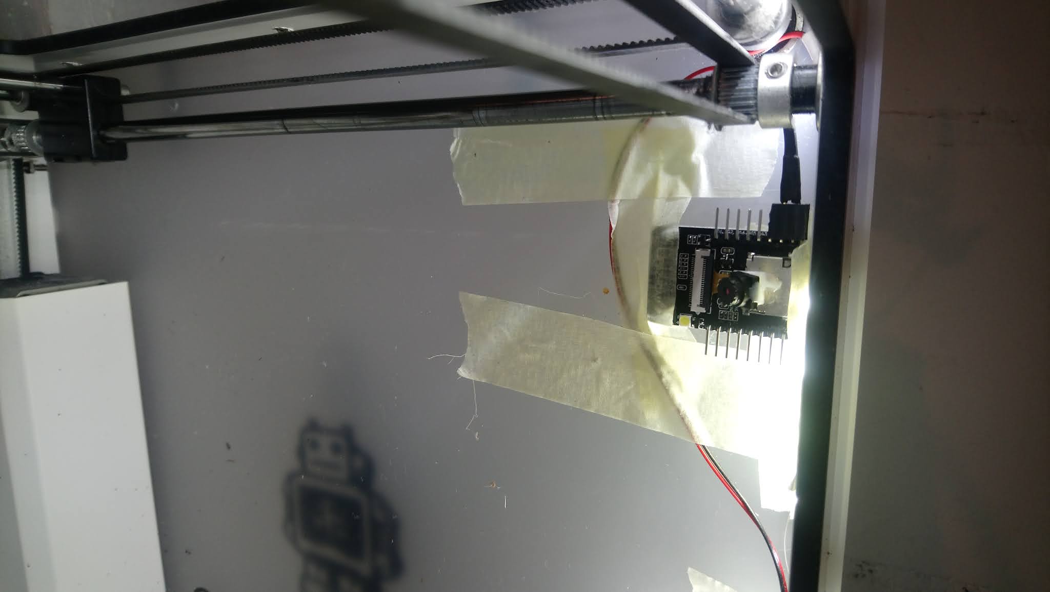
The second camera is placed in the 3D printer with tape, and I slid a 45° block below the camera module to get the right angle.

These cameras produce a new image roughly every 3 minutes, so I have a lot of training data by now. The images look like this:


The images can be classified into different categories:

  1. Idle: The printhead is in its parking position and the printbed is empty
  2. Preparing: The printhead is in the front left position and the printer is heating up
  3. Printing: I don't really have to explain this I guess
  4. Finished: The printhead is in its parking position and the printbed is not empty
  5. Problem: A distance between the printbed or the current object and the nozzle is visible
  6. Maintenance: My hands are in the printer, the printhead is disassembled or not in its parking position
  7. Off: All lights are switched off and the image is only dark

Camera 1 can't really decide whether it's printing or problem, so this camera cannot detect "problem", camera 2 can't distinguish between idle and finished, so this camera cannot detect "finished".

I sorted the first images I had into the 7 categories and then trained a neural net on them. My architecture of the net (in Tensorflow, Python) looks like this:

model = models.Sequential()
model.add(layers.Conv2D(32, (5, 5), activation='relu', input_shape=(128, 128, 3)))
model.add(layers.MaxPooling2D((2, 2)))
model.add(layers.Conv2D(32, (3, 3), activation='relu'))
model.add(layers.MaxPooling2D((2, 2)))
model.add(layers.Conv2D(32, (3, 3), activation='relu'))
model.add(layers.MaxPooling2D((2, 2)))
model.add(layers.Conv2D(32, (3, 3), activation='relu'))
model.add(layers.MaxPooling2D((2, 2)))
model.add(layers.Conv2D(32, (3, 3), activation='relu'))
model.add(layers.MaxPooling2D((2, 2)))
model.add(layers.Flatten())
model.add(layers.Dense(64, activation='relu'))
model.add(layers.Dense(7))

It is designed for the input of 128x128 pixel images with 3 colours and consists of 5 convolutional layers, each with a max pooling layer afterwards and then one fully connected layer with 64 neurons which leads to the output layer with 7 neurons.

To further optimise the detection, I added a second net that uses images of the input 64x64 pixels and thus has only 4 convolutional layers. The result percentages for each category of the two nets are added (and divided by 2), which increases the accuracy. In the end, this result is obtained for both cameras and again added, furthermore there is a microphone inside the printed which measures the noise level and can distinguish whether the printhead fan is on or off and thereby delivers another input. The total results then creates a forecast for the status of the printer. As described in the previous post, this status is then sent to my IoT system which alerts me if

  • The printer status changes to "Problem"
  • The printer status changes to "Finished"

Tuesday, 2 July 2019

WiFi thermometer with the DHT22 and EPS8266-12E

(Deutsche Version) I should be posting more stuff about the printer but I just worked on the ESP8266-12E and realised a super easy WiFi thermometer (using an EPS8266-12E as a web client which sends to an apache server on a raspberry pi), so I wanted to share this here.


1. The ESP8266-12E
The ESP8266-12E is an Arduino like microcontroller which has an integrated WiFi controller. If you look for it on google, you'll find many sources to aquire it. The great thing about this EPS8266 is that you can program it with the Arduino software, so all your libraries work, too!

2. Set up the Arduino IDE for the ESP8266-12E
First you should install the CH340 driver. There are many tutorials for this on the internet so I will not explain this. After installing the driver, you have to switch to the Arduino settings (I only have a german Arduino IDE but I guess you should be able to figure out where to click):

Here you add the board manager URL:
http://arduino.esp8266.com/stable/package_esp8266com_index.json

Afterwards, you can download the settings for the boards in the board manager:

Look for "ESP8266" and install it:

Now, everything should be set up and we can choose the board, I used "NodeMCU 1.2 (ESP8266-12E Module)":


3. The code
The code is quite straight-forward. You have to put in your WiFi login data, afterwards the DHT22 sensor is initialised. In "loop", the connection to the WiFi is tested. If a connection is established, the sensor measures temperature and humidity (float t and float h), these values are stored in a string (requestString) and then sent as HTTP get request to the server. The code for the server is posted below.

#include <ESP8266WiFi.h>
#include <ESP8266HTTPClient.h>
const char* ssid     = "***";
const char* password = "***";   
int wifiStatus;
    
#include "DHT.h"
#define DHTPIN D2
#define DHTTYPE DHT22
DHT dht(DHTPIN, DHTTYPE);

void setup() {
  Serial.begin(9600);
  // put your setup code here, to run once:

  Serial.print("Your are connecting to;");
  Serial.println(ssid);
  
  WiFi.begin(ssid, password);
  
  while (WiFi.status() != WL_CONNECTED)
  {
    delay(500);
    Serial.print(".");
  }

  dht.begin();
}

void loop() {
  // put your main code here, to run repeatedly:
  wifiStatus = WiFi.status();
  
  if(wifiStatus == WL_CONNECTED){
    Serial.println("");
    Serial.println("Your ESP is connected!");  
    Serial.println("Your IP address is: ");
    Serial.println(WiFi.localIP()); 
    float t = dht.readTemperature(); 
    float h = dht.readHumidity(); 
    HTTPClient http;
    char requestString[255] = "";
    sprintf(requestString, "http://webServer.de/Send.php?name=TemperatureSensor&data=%f,%f", t, h);
    http.begin(requestString);  //Specify request destination
    int httpCode = http.GET();                                                                  //Send the request
    
    if (httpCode > 0) 
    { //Check the returning code
      String payload = http.getString();   //Get the request response payload
      Serial.println(payload);                     //Print the response payload
    }
    
    http.end();   //Close connection
    
    delay(300000);
  }
  else{
    Serial.println("");
    Serial.println("WiFi not connected");
    delay(1000);
  }
}

4. The Sserver code
An apache server is running on my raspberry pi. In /var/www, there is a file "Send.php", which simply receives sensor data and saves this to .csv files. The sensor tells its name in the get command, this is the filename where the data is stored. The current time is added and stored together with the data at the end of the file. In this case, this is the temperature in °C and the humidity in %.

<html>
 <head>
  <title>Send Sensor Values</title>
 </head>
 <body>
  <?php

$name = htmlspecialchars($_GET["name"]);
$data = htmlspecialchars($_GET["data"]);

$date = date("Y-m-d") . "T" . date("H:i:s.u") . "Z";

$file = "data/".$name.".csv";
$Saved_File = fopen($file, 'a');
fwrite($Saved_File, $date . "," . $data . "\r\n");
fclose($Saved_File);

  ?>
 </body>
</html>

Sunday, 11 September 2016

Read DHT11 sensor with Arduino

(Deutsche Version) Some time ago, I bought a temperature and humidity sensor which is called DHT11. The sensor is easy to use and can be used with 3.3V or 5V. The sensor has four pins, for the normal operation, only three of them are needed.
The left pin (as you can see in the image) is connected to 5V, the pin on the right with GND. The left pin of the middle pins is the signal pin which can be connected with a random digital pin on the arduino (in my example, this is pin 2). Additionally, a 10k resistor is needed between the data pin and 5V.

Next, you need the corresponding library which you can download here: Download. In the arduino software the sensor can be read as it is shown in the following example. The source code should be self-explainatory. If a sensor with a higher precision is needed, you can use a DHT22, therefore you just have to adjust the DHTTYPE definition.

#include "DHT.h"
#define DHTPIN 2

#define DHTTYPE DHT11

DHT dht(DHTPIN, DHTTYPE);

void setup() {
  Serial.begin(9600);

  dht.begin();
}

void loop() {
  float h = dht.readHumidity();
  float t = dht.readTemperature();
  
  Serial.print("Humidity: ");
  Serial.print(h);
  Serial.print(" %\t");
  Serial.print("Temperature: ");
  Serial.print(t);
  Serial.println(" *C ");

  delay(2000);
}

Monday, 9 June 2014

BH1750FVI Light Sensor

(Deutsche Version) For my home automation project I want to control my shutters automatically. The shutters should be closed when the sun is shining into my room to keep the heat outside. To detect the sun I want to measure light intensity and temperature.

To measure the light intensity I use a BH1750FVI light sensor which you can buy at Ebay for about 2€.

The sensor measures the light intensity/brightness between 0 and 65535 lx and sends the measured value via I2C to your microcontroller. Measurement can be done recurring or non-recurring with a resolution of 0.5, 1 or 4 lx.

Controlling the sensor and reading the values can be done very easy using Arduino and the library created by Christopher Laws.

After connecting the sensor to 5V supply voltage and the SDA/SCL pins of your Arduino, ATmega or ATtiny you can flash the example code provided with the library:

#include <Wire.h>
#include <BH1750.h>

BH1750 lightMeter;

void setup(){
  Serial.begin(9600);
  lightMeter.begin();
  Serial.println("Running...");
}


void loop() {
  uint16_t lux = lightMeter.readLightLevel();
  Serial.print("Light: ");
  Serial.print(lux);
  Serial.println(" lx");
  delay(1000);
} 
 
The code is self-explanatory. In  setup() the sensor is initliazed using the begin()-function. If you want to you can set the measurement mode here by providing different parameters. See the h-file of the library for further information. After the initialization the light intensity/brightness in Lux can read using the readLightLevel() command. And that's it, there's nothing more to say ;)