This program shows the disk space usage of a partition clearly arranged as you can see in the following image:
A collection of my projects in the areas of physics, electronics and information science.
AdSense
Sunday, 5 October 2014
Show disk space usage clearly arranged - WinDirStat
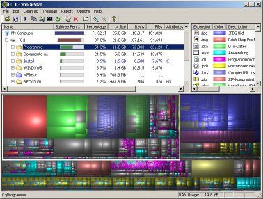
(Deutsche Version) With increasing data volume, it gets harder to keep track of all your data and so it can easily happen that the hard drive is full and you don't know which files are responsible for this. To face this problem, there is a useful program: WinDirStat.
This program shows the disk space usage of a partition clearly arranged as you can see in the following image:
You can now select folders and a white border will appear around the disk usage of the whole folder. Every file is represented by a rectangle so you can easily spot big files. Personally, I deleted lots of gigabytes of unnecessary files and can recommend this program to everyone.
This program shows the disk space usage of a partition clearly arranged as you can see in the following image:
Sunday, 31 August 2014
Arduino, ATmega or ATtiny: monitor supply voltage
(Deutsche Version)
If you supply your Arduino or ATmega/ATtiny using a battery you might want to be warned, when the battery is almost empty so you can replace it. To do this you can monitor the supply voltage. If it drops below a defined threshold you can for example turn on a LED to be warned.
Monitoring the voltage can be done without any additional hardware by using the microcontrollers analog digital converter. As you might know, the value of the ADC is calculated using the following formula:
VALUE_ADC = V_INPUT * 1023/V_REF
Now you could think: "I'll just take my supply voltage as input voltage for the ADC" but that won't work since the supply voltage is also used as reference voltage. The value of the ADC would always be 1023.
But there is a trick: every microcontroller generates an internal reference voltage, the so called "bandgap voltage" V_BG. At the ATmega328 which is used in die Arduino Uno, the bandgap voltage is 1.1V. You can use this voltage as input für your ADC.
With V_INPUT = V_BG and V_REF = V_CC you get:
VALUE_ADC = V_BG * 1023/V_CC
or:
V_CC = V_BG * 1023/VALUE_ADC
With V_BG = 1100 (in mV) you get:
V_CC = 1100 * 1023/VALUE_ADC
Where V_CC is the value of your supply voltage in mV.
The code for the Arduino Uni is:
In loop() the measurement is started by setting the bit ADSC. When it's finished (bit ADSC is cleared) the result of the conversion is read from the registers ADCL (lower 8 bits) and ADCH (upper 2 bits) and merged to a 10-bit-result. Using this result, the supply voltage is calculated. If it is uner 5V, the LED is turned on.
This method works with every ATmega oder ATtiny. Depending on the µC you might have to set different bits in the registers of the ADC. Check the datasheet of your microcontroller.
If you supply your Arduino or ATmega/ATtiny using a battery you might want to be warned, when the battery is almost empty so you can replace it. To do this you can monitor the supply voltage. If it drops below a defined threshold you can for example turn on a LED to be warned.
Monitoring the voltage can be done without any additional hardware by using the microcontrollers analog digital converter. As you might know, the value of the ADC is calculated using the following formula:
VALUE_ADC = V_INPUT * 1023/V_REF
Now you could think: "I'll just take my supply voltage as input voltage for the ADC" but that won't work since the supply voltage is also used as reference voltage. The value of the ADC would always be 1023.
But there is a trick: every microcontroller generates an internal reference voltage, the so called "bandgap voltage" V_BG. At the ATmega328 which is used in die Arduino Uno, the bandgap voltage is 1.1V. You can use this voltage as input für your ADC.
With V_INPUT = V_BG and V_REF = V_CC you get:
VALUE_ADC = V_BG * 1023/V_CC
or:
V_CC = V_BG * 1023/VALUE_ADC
With V_BG = 1100 (in mV) you get:
V_CC = 1100 * 1023/VALUE_ADC
Where V_CC is the value of your supply voltage in mV.
The code for the Arduino Uni is:
int led = 13; //pin of the LED int adc_low, adc_high; //buffer for the results of the ADC long adc_result; //10bit result of measurement of ADC long vcc; //supply voltage void setup() { pinMode(led, OUTPUT); ADMUX |= (1<<REFS0); //VCC as reference for ADC ADMUX |= (1<<MUX3) | (1<<MUX2) | (1<<MUX1); //1.1V bandgap voltage as input of ADC delay(10); //wait until reference voltage is set ADCSRA |= (1<<ADEN); //enable ADC } // the loop routine runs over and over again forever: void loop() { ADCSRA |= (1<<ADSC); //start measurement while (bitRead(ADCSRA, ADSC)); //wait until measurement is completed //buffer results. Important: read ADCL first! adc_low = ADCL; adc_high = ADCH; adc_result = (adc_high<<8) | adc_low; //10bit result vcc = 1125300L / adc_result; //calculate supply voltage in mV (1100mV * 1023 = 1125300) //if supply voltage is lower then 5V if (vcc < 5000) { digitalWrite(led, HIGH); //turn on LED } else { digitalWrite(led, LOW); //turn of LED } delay(500); }
In setup()-function the ADC is configured to use the supply voltage V_CC als referenz and the bandgap voltage V_BG as input. Then the ADC is enabled.
In loop() the measurement is started by setting the bit ADSC. When it's finished (bit ADSC is cleared) the result of the conversion is read from the registers ADCL (lower 8 bits) and ADCH (upper 2 bits) and merged to a 10-bit-result. Using this result, the supply voltage is calculated. If it is uner 5V, the LED is turned on.
This method works with every ATmega oder ATtiny. Depending on the µC you might have to set different bits in the registers of the ADC. Check the datasheet of your microcontroller.
Wednesday, 20 August 2014
ATmega - measure the soil humidity
(Deutsche Version) Today, I want to present a humidity sensor. The basic idea is to measure the soil humidity at plants to know when you have to water the plants.
To construct the sensor, you don't need much stuff. I used a small piece of stripboard, two nails and some pin strips. The sensor looks like this:
The next step is to measure the resistivity in between the two nails (when the sensor is in the earth) and then you can estimate the soil humidity. The electrical wiring is the following:
If the earth is humid, the sensor conducts well, therefore the ATmega measures a high voltage, if the earth is dry, the measured voltage is small. You can now think about putting units on the axis, in my opinion, it is sufficient to simply plot the "humidity" from 0 to 5 V and then check the voltage which corresponds to dry earth which has to be watered. This can now be displayed by an LED or by sending an automatic e-mail.
To construct the sensor, you don't need much stuff. I used a small piece of stripboard, two nails and some pin strips. The sensor looks like this:
The next step is to measure the resistivity in between the two nails (when the sensor is in the earth) and then you can estimate the soil humidity. The electrical wiring is the following:
If the earth is humid, the sensor conducts well, therefore the ATmega measures a high voltage, if the earth is dry, the measured voltage is small. You can now think about putting units on the axis, in my opinion, it is sufficient to simply plot the "humidity" from 0 to 5 V and then check the voltage which corresponds to dry earth which has to be watered. This can now be displayed by an LED or by sending an automatic e-mail.
Monday, 9 June 2014
BH1750FVI Light Sensor
(Deutsche Version) For my home automation project I want to control my shutters automatically. The shutters should be closed when the sun is shining into my room to keep the heat outside. To detect the sun I want to measure light intensity and temperature.
To measure the light intensity I use a BH1750FVI light sensor which you can buy at Ebay for about 2€.
The sensor measures the light intensity/brightness between 0 and 65535 lx and sends the measured value via I2C to your microcontroller. Measurement can be done recurring or non-recurring with a resolution of 0.5, 1 or 4 lx.
Controlling the sensor and reading the values can be done very easy using Arduino and the library created by Christopher Laws.
After connecting the sensor to 5V supply voltage and the SDA/SCL pins of your Arduino, ATmega or ATtiny you can flash the example code provided with the library:
To measure the light intensity I use a BH1750FVI light sensor which you can buy at Ebay for about 2€.
The sensor measures the light intensity/brightness between 0 and 65535 lx and sends the measured value via I2C to your microcontroller. Measurement can be done recurring or non-recurring with a resolution of 0.5, 1 or 4 lx.
Controlling the sensor and reading the values can be done very easy using Arduino and the library created by Christopher Laws.
After connecting the sensor to 5V supply voltage and the SDA/SCL pins of your Arduino, ATmega or ATtiny you can flash the example code provided with the library:
#include <Wire.h> #include <BH1750.h> BH1750 lightMeter; void setup(){ Serial.begin(9600); lightMeter.begin(); Serial.println("Running..."); } void loop() { uint16_t lux = lightMeter.readLightLevel(); Serial.print("Light: "); Serial.print(lux); Serial.println(" lx"); delay(1000); }
The code is self-explanatory. In setup() the sensor is initliazed using the begin()-function. If you want to you can set the measurement mode here by providing different parameters. See the h-file of the library for further information. After the initialization the light intensity/brightness in Lux can read using the readLightLevel() command. And that's it, there's nothing more to say ;)
Labels:
Arduino,
ATMega,
ATtiny,
Home Automation
Wednesday, 23 April 2014
Arduino - I2C scanner
(Deutsche Version) Today, I want to present a simple I2C scanner. The basic functionality is simple: A counter starts at 0 and tries to reach an I2C device. If this fails, the counter increases and checks at the next address. The source code is the following:
Instead of lcd.print, you can use any other kind of output. As soon as a device is found, the Arduino waits a second and then continues scanning.
for (int i = 0; i < 120; i++)
{
Wire.beginTransmission(i);
error = Wire.endTransmission();
sprintf(buf, "scan %i - %i",i,error);
lcd.setCursor(0,1);
lcd.print(buf);
if (error == 0)
{
//success!
delay(1000);
}
}
Instead of lcd.print, you can use any other kind of output. As soon as a device is found, the Arduino waits a second and then continues scanning.
Labels:
Arduino
Sunday, 23 March 2014
Mobile phone - camera occlusion scratched, photos blurred
(Deutsche Version) My brother owns an HTC Desire Z. For quite some time, all the photos he takes are blurred. Looking at the camera occlusion reveals the reason: The centre of the occlusion is scratched, only the edge looks ok.
The problem is the anti reflection coating on the camera occlution. On the one hand, this creates nice pictures, but when it is scratched, it is nothing worth at all.
The solution for the problem is now to polish the whole coating away. Therefore you have to take some toothpaste and a cotton bud and rub it for about 2 minutes. Afterwards it should look like this:
There is a difference in the qualities of the shown pictures. Nevertheless the quality after polishing is much better compared to a scratched camera occlusion where all pictures were blurred.
![]() |
| Slightly scratched camera occlusion, picture taken through a polished camera occlusion. |
The solution for the problem is now to polish the whole coating away. Therefore you have to take some toothpaste and a cotton bud and rub it for about 2 minutes. Afterwards it should look like this:
![]() |
| Polished camera occlusion, picture taken through a not polished camera occlusion. |
Sunday, 2 March 2014
Register pointer - accessing specific registers via I2C with Arduino
(Deutsche Version) Sometimes when using I2C you want to access a specific register of your I2C-save for reading and writing, e.g. when usingthe real time clock DS1307. This can be done using the so called register pointers. As you cann guess by the name, these pointers point to the register you want to read or write.
This is pretty easy to use: when writing via I2C, the first byte written with the write()-command sets the register pointer to the desired register. An example using the DS1307:
Reading data from a specific register works similar:
This is pretty easy to use: when writing via I2C, the first byte written with the write()-command sets the register pointer to the desired register. An example using the DS1307:
Wire.beginTransmission(DS1307_ADDRESS); Wire.write(0x02); //set pointer to register 2 Wire.write(decToBcd(hour)); //write value for hours in register 2
Wire.write(decToBcd(weekDay)); //write value for weekday in register 3
Wire.endTransmission();The first byte written after beginTransmission() sets the pointer to register 2 (where the hours are stored). With the second write()-command the value itself is written to the register. Then the pointer is automatically set to the next register, so the following write()-command writes to register 3.
Reading data from a specific register works similar:
Wire.beginTransmission(DS1307_ADDRESS); Wire.write(0x02); //set pointer to register 2 Wire.endTransmission(); Wire.requestFrom(DS1307_ADDRESS, 7);//begin data request from register 2 int hour = bcdToDec(Wire.read()); //read hours from register 2 int weekDay = bcdToDec(Wire.read()); //read weekday from register 3Like in the first example, the pointer is set to register 2. Then we can request data using the reguestFrom()-command. After that, read() reads data from register 2. After reading, the pointer is automatically set to the next register, so the following read()-command reads from register 3.
Subscribe to:
Posts (Atom)


