AdSense

Saturday, 31 August 2013

Read acceleration sensor MPU-6050 with ATMega 16A

(Deutsche Version) In this post, I will show how to read the values of an MPU-6050 with an ATMega 16A. For the usage of I2C on the ATMega, I use this implementation.

If you want to use a Raspberry PI instead of an ATMega, see this post.

At first, I wrote two functions which can read from a register respectively write to a register:

void TWIM_WriteRegister(char reg, char value)
{
    TWIM_Start(addr, TWIM_WRITE); // set device address and write mode
    TWIM_Write(reg);
    TWIM_Write(value);
    TWIM_Stop();
}

char TWIM_ReadRegister(char reg)
{
    TWIM_Start(addr, TWIM_WRITE);
    TWIM_Write(reg);
    TWIM_Stop();

    TWIM_Start(addr, TWIM_READ); // set device address and read mode
    char ret = TWIM_ReadNack();
    TWIM_Stop();
    return ret;
}


As a second step, I wrote two functions which read the acceleration and gyro data from the Sensor. Please note that you have to disable the sleep mode, this can be done by using TWIM_WriteRegister(107, 0).

double MPU6050_ReadAccel(int axis)//x = 0; y = 1; z = 2
{
  char reg = axis * 2 + 59;
  char AFS_SEL = TWIM_ReadRegister(28);
  double factor = 1<<AFS_SEL;
  factor = 16384/factor;
  int val = 0;
  double double_val = 0;
  char ret = 0;

  ret = TWIM_ReadRegister(reg);
  val = ret << 8;

  ret = TWIM_ReadRegister(reg+1);  
  val += ret;

  if (val & 1<<15)
  val -= 1<<16;

  
  double_val = val;

  double_val = double_val / factor;

  return double_val;
}

double MPU6050_ReadGyro(int axis)//x = 0; y = 1; z = 2
{
  char reg = axis * 2 + 67;
  char FS_SEL = TWIM_ReadRegister(27);
  double factor = 1<<FS_SEL;
  factor = 131/factor;
  int val = 0;
  double double_val = 0;
  char ret = 0;

  ret = TWIM_ReadRegister(reg);
  val = ret << 8;

  ret = TWIM_ReadRegister(reg+1);  
  val += ret;

  if (val & 1<<15)
  val -= 1<<16;


  double_val = val;
 
  double_val = double_val / factor;

  return double_val;
}


The values for the gyrometer are in degrees per second and in units of g for the accelerometer, further information is provided in the Register Map, especially at the explaination of FS_SEL and AFS_SEL: http://www.invensense.com/mems/gyro/documents/RM-MPU-6000A.pdf

Thursday, 29 August 2013

Header image depending on the time of day

I created a homepage where I wanted to change the header image depending on the time of day. In the daytime I wanted an image of a building by day, in the nighttime an image of the same building by night.

This can be done pretty easy with PHP.

At first the current time hast to be  stored in variable:

$time = date("G", time())

time() function returns the UNIX timestamp of the server. The UNIX timestamp is the number of seconds since 01.01.1979 at 1 AM. To get the timestamp to a "readable" format we use the date() function. The format is chose with the first paramter. "G" delivers the the hours without leading zero. A lot of other formats are possible, you can find them on this website.

The current hour is saved in the variable called $time. It is important to know that time is stored in UTC (coordinated universal time). I needed MEZ (or MESZ) so I had to add one (two) hours.

Now the header image can be chosen according to the current time:

if ($time > 7 && $time < 21 ) {
   $path = "http://yourserversdomain.de/images/header_day.jpg";
 }

else {
    $path = "http://yourserversdomain.de/images/header_night.jpg";
}

If the number of hours is greater than 7 and less than 21 (it is between 8:00 and 20:59) the path of the "day image" is stored to the variable $path - else the path of the "night image".


Then the image is embedded using HTML:

<img src="<?php echo $path; ?>" width="123" height="456" alt="" />


Of course you could also use this method for creating images depending on the weekday or the season.

Wednesday, 28 August 2013

Arduino code on ATtiny

As you can read in my last posts I am working at a remite control at the moment. For this purpose the "normal" ATmega8 isn't the best choice (too big, too expensive, 5V supply voltage). So the project is based on an ATtiny, but I still want to use the features and the libraries of the Arduino IDE. How you can use the IDE to programm an ATmega8 can be read in my first post on this blog. It was pretty easy because Arduino supports the ATmega8 out of the box.
For the ATtiny, a few more steps have to be taken. With the following instructions you can add the ATtiny45, ATtiny85, ATtiny24, ATtiny44 and ATtiny84 to the Arduino IDE.

First of all you have to download this file. The containing folder "attiny" must be copied to the folder "hardware" in your Arduino installation. It should look like this: "C:\Programs\Arduino\hardware\attiny".


The folder contains the file "boards.txt". It contains the information to the used "boards" (fuse settings, clock frequency,...) - in our case it's only the ATiny. Only the "boards" listed in this file will appear in the IDE. The file only includes the settings for the use of the internal clock source. For an external clock source, you have to adapt the settings. In this case it's important so set the correct fuses, otherwise you will have timing problems.

Now you have to tell the IDE the pin settings of your ATTiny. The folder "variants" in the archive you just downloaded  contains the subfolders "tiny8" and "tiny14". In these folders you can find a file named "pins_arduino.h" which specifies the pin mapping of the Tiny. In the file you can also see which pin of the ATtiny has which "Arduino function". For ATTiny24/44/84 this would be for example


                                          +-\/-+
                                VCC  1|    |14  GND
                      (D 10)  PB0  2|    |13  AREF (D  0)
                       (D  9)  PB1  3|    |12  PA1  (D  1)
                                 PB3  4|    |11  PA2  (D  2)
    PWM  INT0  (D  8)  PB2  5|    |10  PA3  (D  3)
       PWM        (D  7)  PA7  6|    |9   PA4  (D  4)
       PWM        (D  6)  PA6  7|    |8   PA5  (D  5)        PWM
                                          +----+

When you start the Arduino IDE, you should see the ATtiny under "Tools-Board":

From now on, it's business as usual. Depending on the used ATiny, there might be some restrictions, e.g. with interrupts. Furthermore your have to use a programmer like the USBasp to programm the Tiny.

These instructions are also valid for every other ATtiny (and ATmega) - you just have to find the right "pins_arduino.h" or create it for yourself.

C# WPF - DataBinding

(Deutsche Version) DataBindings in WPF are very powerful and useful. Today, I will explain the basics. The basic idea is: I have a display element and a variable (technically: field). When I change my variable, I want the display element to change and vice versa, so the variable will change if the display element changes (e.g. a text is entered into a TextBox). At first the XAML part of the code:

<TextBox Name="InputText" Grid.Row="0" Text="{Binding BindingText, UpdateSourceTrigger=PropertyChanged, Mode=TwoWay}"></TextBox>
<TextBlock Name="OutputText" Grid.Row="1" Text="{Binding BindingText, UpdateSourceTrigger=PropertyChanged, Mode=OneWay}"></TextBlock>


As a next step, I need an object to which I am doing the DataBinding. In my case, this is the class "AnyClass" which containt the field "BindingText". I could also simply use MainWindow.xaml.cs. To define the object to which the bining should be, you have to do the following:

AnyClass anyClass = new AnyClass();
InputText.DataContext = anyClass;
OutputText.DataContext = anyClass;


I could also do this.DataContext = anyClass;, this would have the same effect but I want to show different possibilities how to do DataBinding. I also could also create the field "BindingText" in MainWindow.xaml.cs and then do this.DataContext = this;.

Now I want to face the class AnyClass. At first a short introduction to fields. A field can be used just like a variable but it cannot hold values directly. The minimum field would be this:

public string BindingText
{
    get { return _BindingText; }
    set { _BindingText = value; }
}
private string _BindingText = "";


This is a field. The get and set parts can do lots of funny things like checking the input, throw events, and everything else.

Now I will show the class AnyClass which is the last missing part for the DataBinding:

using System;
using System.Collections.Generic;
using System.ComponentModel;
using System.Linq;
using System.Text;
using System.Threading.Tasks;

namespace DataBindingExample
{
    public class AnyClass : INotifyPropertyChanged
    {
        public event PropertyChangedEventHandler PropertyChanged;
        public string BindingText
        {
            get { return _BindingText; }
            set
            {
                _BindingText = value;
                if (this.PropertyChanged != null)
                {
                    this.PropertyChanged(this, new PropertyChangedEventArgs("BindingText"));
                }
            }
        }
        private string _BindingText = "<empty>";
    }
}


By calling PropertyChanged, the display element gets the information that there is a new variable value and refreshes the displayed value. This should cover the basics for DataBinding. If there are further questions, I will answer them in the comments.

 A post about this topic who also covers converters can be found on C# Tips and Tricks.

Friday, 23 August 2013

A music player with C#

(Deutsche Version) There are a lot of music players on this world. Every player has its advantages and disadvantages. Until now, I was not able to find the "perfect" music player. Therefore I wrote my own music player which can be downloaded here. A bit about the handling: At first, a folder has to be specified as music library. Then, by clicking on "Refresh Library", all music files in this directory are laoded. Hotkeys were very important for me, so I implemented them (see below). I will present two important parts of the music player: Playing music with WPF and using Hotkeys. By the way, you can find a basic introduction to WPF here: C# Tips and Tricks.

Playing music

Hence I use WPF, playing music is very simple: In my xaml file, I have a MediaElement:

<MediaElement Height="10" Width ="10"  LoadedBehavior="Manual" Name="mediaElement1" VerticalAlignment="Top" />

The MediaElement is invisible. To play music, you have to execute the following code:

mediaElement1.Source = new Uri(pathToMediaFile);
mediaElement1.Play();


This is the whole magic for playing music. You can now do several things like registering to events so you know when the actual song has finished playing (to start the next song).

Hotkeys

Note: By now I use a "better" implementation of the hotkeys which you can find here.

Using hotkeys is pretty simple. At first, you have to add several lines into the program:

[DllImport("User32.dll")]
private static extern bool RegisterHotKey(
    [In] IntPtr hWnd,
    [In] int id,
    [In] uint fsModifiers,
    [In] uint vk);

[DllImport("User32.dll")]
private static extern bool UnregisterHotKey(
    [In] IntPtr hWnd,
    [In] int id);

private HwndSource _source;
private const int HOTKEY_ID = 9000;

protected override void OnSourceInitialized(EventArgs e)
{
    base.OnSourceInitialized(e);
    var helper = new WindowInteropHelper(this);
    _source = HwndSource.FromHwnd(helper.Handle);
    _source.AddHook(HwndHook);
    RegisterHotKey();
}

protected override void OnClosed(EventArgs e)
{
    _source.RemoveHook(HwndHook);
    _source = null;
    UnregisterHotKey();
    base.OnClosed(e);
}

private void UnregisterHotKey()
{
    var helper = new WindowInteropHelper(this);
    UnregisterHotKey(helper.Handle, HOTKEY_ID);
}

private IntPtr HwndHook(IntPtr hwnd, int msg, IntPtr wParam, IntPtr lParam, ref bool handled)
{
    const int WM_HOTKEY = 0x0312;
    switch (msg)
    {
        case WM_HOTKEY:
            OnHotKeyPressed(wParam.ToInt32());
            break;
    }
    return IntPtr.Zero;
}


As a next step, I defined the three hotkeys I need:

private void RegisterHotKey()
{
    var helper = new WindowInteropHelper(this);
    const uint VK_RIGHT = 0x27;
    const uint VK_LEFT = 0x25;
    const uint VK_SPACE = 0x20;
    const uint MOD_ALT = 0x0001;
    const uint MOD_CTRL = 0x0002;

    if (!RegisterHotKey(helper.Handle, HOTKEY_ID+2, MOD_CTRL + MOD_ALT, VK_RIGHT))
    {
        // handle error
    }
    if (!RegisterHotKey(helper.Handle, HOTKEY_ID+1, MOD_CTRL + MOD_ALT, VK_LEFT))
    {
        // handle error
    }
    if (!RegisterHotKey(helper.Handle, HOTKEY_ID, MOD_CTRL + MOD_ALT, VK_SPACE))
    {
        // handle error
    }
}


Finally, I need a function which executes the desired actions when a hotkey is pressed:

private void OnHotKeyPressed(int key)//9000 = space, 9001 = left, 9002 = right
{
    //System.Console.Write("KeyPressed! {0}\n", key);
    switch (key)
    {
        case 9000: if (playing) { pause(); } else { play(); }
            break;
        case 9001: back();
            break;
        case 9002: next();
            break;
        default:
            break;
    }
    // do stuff
}


Please note: If you have a hotkey registered, e.g. "AltGr" + "0", this key combination is only available for my program. So in this example, I could not write } anymore (I have a german keyboard layout) as long as my program is opened.

Wednesday, 21 August 2013

PHP - Make chat on own server "safe"

(Deutsche Version) Realising a chat with PHP is not difficult. After a short time one should recognize that this chat can also execute HTML code (e.g. images). This means that PHP code can be executed, too. This is a huge security issue, anyone could format the hard drive of the server or anything else.

To prevent any execution of code, you can do the following: Before displaying the chat message, replace every < Symbol with the HTML equivalent. This is &lt;. In PHP this can be realised this way: $chatMessage = str_replace("<", "&lt;", $chatMessage);. Now no PHP and HTML code can be executed anymore. If you want to allow several HTML tags (image, link), you could try to detect this and then not replace the < Symbol.

Arduino as logic analyzer

As promised in my "Home Automation" postings I am going to explain how to use your Arduino Uno as a logic analyzer.

Firt of all you have to download the required software für the Arduino. it can be found here. Depending on the sampling rate you need (2/4 MHz or 1 MHz) you have to choose the correct sketch and upload it to your Arduino. You also have to download the file "ols.profile-agla.cfg" - we will need it later.


After having uploaded the sketch to the Arduino, you can start the serial monitor, switch to 115200 Baud and send 1 or 2 via serial connection to your Arduino. If you receive some kind of status report, everything works fine.


For the next step we will need a software which displays the logged data on the computer. We will use the tool "Logic Sniffer". It's written in Java, so it can be used with Windows and Linux. Download the latest version and unzip it. Copy the file "ols.profile-agla.cfg" to the folder "plugins" and start the programm with "run.bat" or "run.sh". 

You should see the user interface:
Click "Capture"-"Begin capture" - the following window is opened:
Here you have to set the COM-Port of your Arduino, set the correct baude rate and choose Arduino as "Device type". Click "Show devive metadata" to see if everything works as planned.
In the tab "Acquisition" you can set details like sampling rate and so on.
In "Triggers" tab you can enable the triggers. If you tick a channel in "Mask" row, it will be started by a trigger. If "Value" is ticked, it will be triggered by a HIGH signal, otherwise a LOW signal. With "Before/After ratio" you can decide which period before and after the trigger is logged. In the example we will log 5% of the time BEFORE and 95% of the time AFTER the trigger signal.

Now you can connect the signal you want to analyze to the Arduino. Channel 0 is connected to pin 8, channel 1 is pin 9 and so so. 6 channels are supported.


When everything is prepared, you can click the "Capture" button. You should see your signal on the screen:

Of course this logic analyzer isn't as good as the "big" (and expensive) ones. The biggest problem is the limited memory. Only short signals with low sampling rates can be analyzed. But for small projects it should be enough.

Sunday, 18 August 2013

"Home Automation" with Arduino and 433 MHz - The shutters, part 2

(Deutsche Version) Now that we now the theory about controlling the shutters, we can use the theory practically.

As I already mentioned, the protocol to control the shutters is similiar to the protocol used to control the power outlets. So I decided to use the already exisiting rc-switch library. Of course I had to make some changes.

Changes in rc-switch

The library comes with three different protocols for three power outlets. They mostly differ in pulse length and the sync bit. I decided to add a fourth protocol.

The first changes had to be made in the function setProtocol():

void RCSwitch::setProtocol(int nProtocol) {
  this->nProtocol = nProtocol;
  if (nProtocol == 1){
    this->setPulseLength(350);
  }
  else if (nProtocol == 2) {
    this->setPulseLength(650);
  }
  else if (nProtocol == 3) {
    this->setPulseLength(100);
  }
  //edit: protocol 4 for shutters with pulse lenth 250µs and 4 repetitions
  else if (nProtocol == 4) {
    this->setPulseLength(250);
    this->setRepeatTransmit(4);
  }
}


I marked all the changes with an //edit comment. I just added a fourth  else-if for protocol 4. If the user chooses protocol 4, the code sets the pulse length to 250µs and calls the function setRepeatTransmit() with the parameter 4. This means that every command has to be sent four times (like the remote control does).

In the next step I had to add a function which allows sending a quad state command. To do so, I extended the sendTriState() function:

//edit: send quad state command
void RCSwitch::sendQuadState(char* sCodeWord) {
  for (int nRepeat=0; nRepeat<nRepeatTransmit; nRepeat++) {
    //sync bit is sent BEFORE transmission!
 this->sendSync(); 
 int i = 0;
    while (sCodeWord[i] != '\0') {
      switch(sCodeWord[i]) {
        case '0':
          this->sendT0();
        break;
        case 'F':
          this->sendTF();
        break;
        case '1':
          this->sendT1();
        break;
        case 'Q':
          this->sendQQ();
        break;
      }
      i++;
    }   
  }
}


A big difference between shutters and power outlets is the sync bit. When "talking" to the power outlets, the bit hast to be sent AFTER sending the commands. The shutter expects the sync bit BEFORE the command. So the function sendSync() is called before sending the command. The next change was adding a fourth case. If the programm has to send a Q, the function sendQQ() is called (this function was also added by me):

/**
 * edit: Sends a Quad-State "Q" Bit
 *            ___   _
 * Waveform: |   |_| |___
 */
void RCSwitch::sendQQ() {
  this->transmit(3,1);
  this->transmit(1,3);
}

The function sends a long HIGH signal by calling transmit(3,1), follows by a short HIGH signal (transmit(1,3)). The first paramter states the duration of the HIGH signal in pulse lengths. The second paramter states the duration of the LOW signal.


The last changes had to be made in the function which calls the sync bit:

void RCSwitch::sendSync() {

    if (this->nProtocol == 1){
        this->transmit(1,31);
    }
    else if (this->nProtocol == 2) {
        this->transmit(1,10);
    }
    else if (this->nProtocol == 3) {
        this->transmit(1,71);
    }
 
    //edit: snyc bit for shutters
    else if (this->nProtocol == 4) {
        this->transmit(18,6);
    }
}


As we know, the sync bit consists of a HIGH phase with a duration of 4500µs (18 pulse lengths) followed by a LOW phase with a duration of 1500µs (6 pulse lengths)


With these little changes, the rc-switch library can be used to control the shutters.

Testing...

Let's test the library!

#include <RCSwitch.h>

RCSwitch mySwitch = RCSwitch();

void setup() {
  Serial.begin(9600);
  Serial.println("Ready...");
  mySwitch.enableTransmit(10);
  mySwitch.setProtocol(4);
}

void loop() {
  //down
  Serial.println("Down...");
  mySwitch.sendQuadState("0F0F0100QQ0F100F0101");
  mySwitch.sendQuadState("0F0F0100QQ0F100F0110");
  
  delay(5000);
  
  //stop
  Serial.println("Stop...");
  mySwitch.sendQuadState("0F0F0100QQ0F100FFFFF");
  
  delay(1000);
  
  //up
  Serial.println("Up...");
  mySwitch.sendQuadState("0F0F0100QQ0F100F0F0F");
  mySwitch.sendQuadState("0F0F0100QQ0F100F0F1Q");
  
  delay(5000);
  
  //stop
  Serial.println("Stop...");
  mySwitch.sendQuadState("0F0F0100QQ0F100FFFFF");
  
  delay(1000);
}

In the setup() function, the protocol is set to 4. In the loop() function, the new sendQuadState() function is called to send the commands  to move the shutters down, stops them, moves them up and stops them again. How to get these comannds is described in part 1 of this post.

The last step is combining the control of power outlet and shutters to get the desired functionality (power outlet on, move shutters, power outlet off).

Saturday, 17 August 2013

"Home Automation" with Arduino and 433 MHz - The shutters, part 1

(Deutsche Version) As I have shown in my last post, we can successfully communicate with the power outlets so turning on and off the power for the shutters is no problem. The tricky part is communicating with the shutter itself. We only now that communication is done wireless on the 433MHz band but we don't have any information about the used protocol.

Reverse Engineering

To get a rough overview about the used protocol, you have to read the signals sent by the remote control. This could be easily done with a logic analyzer. Unfortunately I don't own such a device. So I googled a little bit and found a way to use the Arduino as a simple logic analyzer. I will describe this in a separate post. Now I just connected the data pin of my 433MHz receiver with the logic analyzer Arduino and I was able to read the signals of the remote control.
When I pushed the “up”-button, I tracked this signal:

“Down” resulted in this signal:

And “stop”:

Transmission is started with some kind of sync bit. The remote control sends a HIGH signal for about 4500µs and a LOW signal for about 1500µs. After that, the data is transmitted. The pattern is similar to the tri-state-system of the power outlets. We have the known states 0, 1 and F and additionally an forth state:
 _ _ _       _
|         | _ |   | _

You could say we have a “quad-state-system”, so I called the forth state Q. The “short” signal has a length of 250µs, the “long” signal has a length of 750µs. Theoretically we could see the signal as a “normal” binary signal: a HIGH signal would be 1, a LOW signal 0. But in my opinion, this would be pretty confusing because we would get pretty long chains of 0s and 1s. Here are the signals in the quad-state-system: Up = 0F0F0100QQ0F100F 0F0F Down = 0F0F0100QQ0F100F 0101 Stop = 0F0F0100QQ0F100F FFFF You can see that the first 16 bits are equivalent, only the last 4 bits differ. I think the first 16 bits are some kind of address, the last 4 bits are the command.

Read the remote control

To read the signal of the remote control, I wrote a program that waits for the signal and prints them in the quad-state-system.

int logfile[40];
int i = 0;
float lastTime = 0;
boolean capturing = false;
boolean checking = false;
boolean dataIncoming = false;

void setup() {
  Serial.begin(9600);
  Serial.println("Ready...");
  pinMode(2, INPUT);
  attachInterrupt(0, handleInterrupt, CHANGE);
}

void loop() {
}

First some variables are declared. Among them is a “logfile” which is used to store the read code. There isn't much to say about the setup() function: the serial connections is started and the interrupt on pin 2 (the receiver module is connected to this pin) is activated here. The interrupt is activated every time the signal at pin 2 is changed. There is even less to say about the loop() function since it's empty. The work is done in the interrupt function:

void handleInterrupt() {

  if (!capturing) {  //if we are not capturing
    if (!checking) {  //if we don't wait for the "start" signal
      if (digitalRead(2) == HIGH) {  //if change from LOW to (now) HIGH
        lastTime = micros();
        checking = true;
      }
    }

    else {    //if we check for the "start" signal
      if ((micros() - lastTime > 4000) && (digitalRead(2) == LOW)) {    //if HIGH was longer than 4000µs and we are LOW now
        checking = false;
        capturing = true;
        lastTime = micros();
      }

      else {
        //that wasn't the "start" signal
        checking = false;
      }
    }
  }

  else {  //we are capturing
    if (!dataIncoming) {  //we haven't received data yet
      if ((micros() - lastTime > 1000) && digitalRead(2) == HIGH) {  //that was the long LOW part before transmission of data
        dataIncoming = true; //now we receive data  
        lastTime = micros();
      }
    }

    else {  //now we receive data
      //if rising flank (now HIGH)
      if (digitalRead(2) == HIGH) {
        //store the time
        lastTime = micros();
      }  

      //if falling flank (now LOW) 
      else if (digitalRead(2) == LOW) {
        //=> check how long we were HIGH
        if (micros() - lastTime > 500) {
          //long
          logfile[i] = 1;
        }

        else {
          //short
          logfile[i] = 0;
        }

        if (i < 39) {
          //as long as we haven't received all bits
          i++;
        }

        else {
          //now we are done
          noInterrupts();  //turn interrupts off
          Serial.println("Empfangene Daten:");
          //print as "quad-bit"
          for (i = 0; i <= 38; i = i + 2) {
            if ((logfile[i] == 0) && (logfile[i+1] == 0))
              Serial.print("0");

            else if ((logfile[i] == 0) && (logfile[i+1] == 1))
              Serial.print("F");

            else if ((logfile[i] == 1) && (logfile[i+1] == 0))
              Serial.print("Q");

            else if ((logfile[i] == 1) && (logfile[i+1] == 1))
              Serial.print("1");
          }
          Serial.println();
          i = 0;
          dataIncoming = false;
          capturing = false;
          interrupts();  //turn interrupts on
          return;  //and begin again
        }
      }

    }
  }
}

I hope the source code is self-explaining. If you have any questions, feel free to ask them in the comments. If you run the program on the Arduino and push a button on the remote control you should see the corresponding code in the serial monitor. I noticed two things I didn't notice when I just analyzed the signal using the logic analyer: 1. every signal is sent four times. I think that is done to prevent errors in transmission 2. the signal for “up” and “down” consists of two command: “up” sends four times the already know command "0F0F0100QQ0F100F 0F0F" followed by the command "0F0F0100QQ0F100F 0F1Q". “down” is four times "0F0F0100QQ0F100F 0101" followed by "0F0F0100QQ0F100F 0110".

"Home Automation" with Arduino and 433 MHz - The power outlet

(Deutsche Version) Like I've already mentioned in my last post,  I want to use my 433MHz modules to control power outlets. You can buy a set of 3 power outlets and a remote control (of course we are not going to need it ;) ) at Pollin for less than 10 Euro: Click me!

To control the power outlets there is a library for Arduino. It's called rc-switch. With these library you can control 433MHz receivers as well as transmitters. There are some examples included to show how the library works.


Transmission protocol

At first I want to explain the basics of the used transmission protocol. The transmitter sends a sequence of bits as HIGH or LOW level. This sequence isn't seen as a binary sequence (only 0 and 1) but as a so called tri-state-sequence. As you can guess by the name, it has THREE STATES. Besides 0 and 1 there is a state called F (F for "floating"). A tri-state-bit is represented by a sequence of HIGH-LOW-HIGH-LOW levels. The order of HIGH and LOW is always the same, the bits are differed by the length of HIGH and LOW level. Either the HIGH phase is longer than the LOW phase or vice versa:
 _ _ _            _
|         | _  or |   | _ _ _

The three states:
 _            _
|   | _ _ _ |  | _ _ _ means 0
 _ _ _       _ _ _                 
|         | _ |        | _ means 1
 _            _ _ _
|   | _ _ _ |        | _ means F

When the user pishes a button on the remote control, it sends the adress of the desired power outlet and the command ("on" or "off"). The transmission is ended with a sync bit.


rc-switch and the power outlets

Actually we don't have to deal with this stuff because rc-switch (our library) supports all kinds of power outlets out of the box.

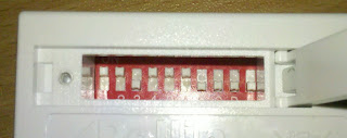
You can set the adress of the power outlet using DIP switches:

If you would use the included remote contol, you would have to set the "system code" using the first 5 switches. With the other 5 switches you can decide wheter the outlet is outlet A, B, C, D or E.
Since we don't use the included remote controle, we don't have to care about this. You can just enter any desired code (in my case it's 11011'10000).

Now you can connect the transmitter module to VCC, GND and a pin of your Arduino and load the following code to the Arduino:

#include <RCSwitch.h>

RCSwitch mySwitch = RCSwitch();

void setup() {

  //transmitter is connected to pin 10  
  mySwitch.enableTransmit(10);
  
}

void loop() {

  //switch power outlet on
  //first parameter is the position of the first 5 DIP switches
  //second parameter is the position of the last 5 switches
  mySwitch.switchOn("11011", "10000");

  //Wait...
  delay(1000);
  
  //switch power outlet off
  mySwitch.switchOff("11011", "10000");
  
  //Wait...
  delay(1000);
  
} 
 
In the setup() function we tell the programm to which pin we connected the transmitter. In loop() we switch on the power outlet, wait for a second, switch it off, wait again and so on.
The commands switchOn and switchOff convert its parameters to a sequence of tri-state-bits, containing the adress and the command: a 1 in the parameter is converted to a 0 in the tri-state-sequence, a 0 will be a F. If we would convert the adress of the used power outlet, it would be: 00F00'0FFFF. The command for switching on the outlet is 0F, the one for switching it off is F0.

So you could replate the switchOn- and switchOff-commands with the sendTriState()-command also included in the library:

void loop() {

  //switch on
  mySwitch.sendTriState("00F000FFFF0F");

  //wait...
  delay(1000);
  
  //switch off
  mySwitch.sendTriState("00F000FFFFF0");
  
  //wait...
  delay(1000);
  
}  


If you don't like tri-state-bits and prefer "real" binary bits, you could convert the tri-state-forman to binary format:
00F00'0FFFF'0F would be 0000010000'0001010101'0001 and 00F00'0FFFF'0F would be 0000010000'0001010101'0100. These sequences could be sent using the command
mySwitch.send("000001000000010101010001");

Sunday, 11 August 2013

"Home Automation" with Arduino and 433 MHz - Basics

Besides the 2.4 GHz wireless modules I presented in some older posts, I am working with modules in 433MHz band. In the upcoming posts, I'm going to share my experience with you.


Basics

There were electrically powered shutters installed in my apartment one year ago. These shutters are remote controlled. This calls for "home automation". You could close the shutters automatically when the sun is shining and when you're on holliday the shuttery can be closed and opened randomly to pretend you're at home.

A quick look at the backside of the remote control showed the following:


It couldn't have been better, the control works on the 433MHz band, a so called ISM band. A lot of remote controlled alarms, power outlet and so on work on this band. That's why there are lot of cheap 433MHz transmitters and receivers. Just look for "433 mhz transmitter receiver" on ebay.

The following combination of transmitter and receiver can be bought for about 1 €.
On the left, there is the receiver, on the right, you can see the transmitter. Both modules have three connections (the second and the third pins of the receiver are connected): VCC, GND and data. When you send a HIGH signal to the data pin of the transmitter, it will send a HIGH signal. With the receiver it's vice versa: when it receives a HIGH signal, the data pin is HIGH. So it's pretty easy to transmit a sequence of bits.


The plan

The motor of the shutter has a "standard" EU plug and is pluged into  power outlet. Unfortunately the shutters consume a lot of energy even when they are in standby mode. It would be very unhandy so unplug the shutters everytime you don't need them. It would be much better to use a remote controlled power outlet. As already mentioned, most of these power outlets work on the 433MHz band. So you can kill two birds with one stone: I want to create a system that can control shutters AND power outlet. In practice, it should work like this: if you want to close the shutters, you press a button. At first, the system turns on the power outlet. Then it sends the "close-signal" to the shutters. When the shutters are closed, the power outlet is switched off.